
How to Design Electronics for Disassembly
If a technician can’t remove the battery or drive in a few minutes with common tools, the design is already creating cost, safety, and waste problems.
I look at design for disassembly as a simple rule: put the parts people need first, use reversible joints, limit tool changes, and test teardown before release. That means planning end-of-life paths early, setting time and fastener targets, using modular layouts, avoiding glued-in parts, and making batteries and storage easy to isolate. It also helps teams recover more material - some systems can recover up to 90% of materials when products come apart cleanly.
Here’s the short version:
Start at the concept stage: define repair, reuse, data removal, parts harvest, and recycling goals.
Set numbers, not vague goals: removal time, fastener count, and tool count for key parts.
Design the structure for access: place batteries, drives, and other high-risk parts near the outer shell.
Use screws, clips, and keyed connectors: avoid glue, potting, and welded seams where possible.
Standardize hardware: fewer screw types and fewer tool changes cut labor.
Test teardown on pre-production units: track time, stuck points, broken clips, and unsafe force.
Label parts and write short work instructions: battery chemistry, drive location, hazards, and power disconnect steps should be easy to find.
In other words: good disassembly design is not about making a product come apart somehow. It’s about making it come apart in the right order, without damage, and without guesswork.
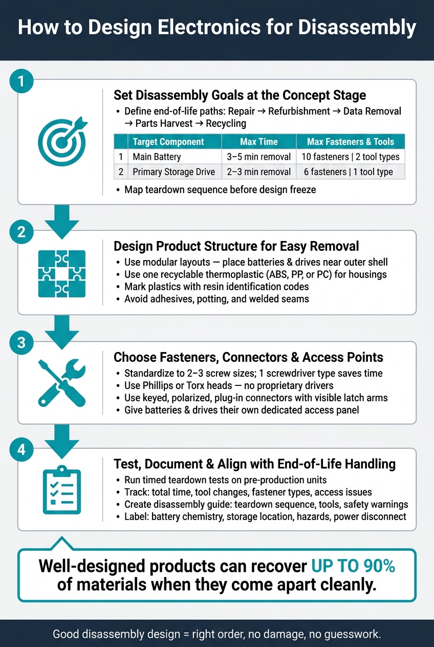
How to Design Electronics for Disassembly: 4-Step Process
How to Design for Disassembly and Recycling
Step 1: Set disassembly goals at the concept stage
Set disassembly goals at the concept stage so end-of-life handling becomes a design requirement, not a late fix. Most teardown headaches are baked in early. If end-of-life handling never makes it into the product requirements document (PRD), it usually gets pushed aside.
The point is simple: define clear teardown requirements before detailed mechanical and electrical design starts. Then treat those requirements the same way you treat performance and cost targets.
Define the end-of-life path for each product
Start by listing every end-of-life path for the product:
Repair
Refurbishment
Secure data removal
Parts harvest
Material recycling
Then rank those paths by value and risk. For many products, secure removal of data-bearing storage comes first because of customer contracts and data protection rules. Repair and refurbishment usually rank ahead of recycling because they keep more value in the product. Hazardous parts, such as lithium-ion batteries and certain PCBs, need a controlled removal path no matter where they land in that ranking.
After that, map specific components to each path. Batteries should go into battery recycling streams. Storage drives should go to secure wiping or physical destruction. High-value parts like displays, CPUs, and power supplies may be worth harvesting for reuse.
Those choices shape the teardown order. In plain terms: the parts that matter most need to come out first.
Set measurable disassembly requirements
Next, turn those priorities into numbers. A line like “make it easy to open” sounds nice, but it won’t hold up in a design review. Clear targets will.
Write requirements that define disassembly performance by removal time, fastener count, and tool changes for each priority part.
Use targets like these:
Component | Max removal time | Max fasteners | Max tool types |
|---|---|---|---|
Main battery | 3–5 minutes | 10 | 2 |
Primary storage drive | 2–3 minutes | 6 | 1 |
Keep power-supply modules removable without exposing technicians to live parts.
This matters for compliance too. California treats e-waste as universal hazardous waste under DTSC rules, so uncontrolled smashing is prohibited. Designs that let workers remove batteries and hazardous modules without damage make compliant handling much easier. California battery stewardship rules also put more pressure on companies to make batteries simple to remove and route into proper stewardship programs.
Map the teardown sequence before finalizing the design
Before design freeze, build a teardown map. Start with the outer covers, move through subassemblies, and finish at the key parts named in your end-of-life ranking.
For each step, document:
The exact tool needed
Fastener type and quantity
Access direction
Any cable or flex-circuit risks
Damage risks
A teardown map is only useful if people can use it on the floor. That’s why it helps to capture the sequence in a table, annotated CAD screenshots, or short video clips. Those formats make the guide easier for repair technicians and ITAD partners to follow during actual work.
Share the draft with end-of-life partners before design freeze. They often catch issues internal teams miss. Then use that teardown map to shape the structural choices in Step 2.
Step 2: Design the product structure for easy removal
Use the teardown map to put the most important modules where someone can reach them first. This part matters more than it may seem. The way you arrange modules, pick materials, and connect parts decides whether a technician opens the device cleanly in a few minutes or ends up wrestling with it.
Use modular layouts and accessible subassemblies
Break the device into self-contained modules that come apart through standard interfaces. Put high-priority parts where they can be removed without taking half the product apart first.
Batteries, storage devices, and other regulated parts should sit near the outer shell or behind a dedicated access panel. If boards and shields are stacked on top of each other, labor goes up fast. So does the risk of tearing a flex cable or cracking the housing.
Cable routing needs the same level of care. Keep cable paths short, direct, and inside a single module when you can. Cables that snake across the whole product and weave through several removable parts are a common cause of damage during teardown.
Once the access path is clean, the next job is simple: cut down the number of materials that have to be separated later.
Reduce material complexity in housings and structural parts
Use one recyclable thermoplastic for housings when possible, such as ABS, polypropylene, or polycarbonate, instead of mixed-material constructions. Skip coatings, metallic finishes, and overmolds that bond different materials together. They add extra separation work and can contaminate polymer streams during recycling.
Mark plastic housings and structural parts with resin identification codes. That gives downstream sorters a clear way to identify and route materials correctly.
Avoid permanent joining methods when possible
Try not to rely on adhesives, potting, or welded seams unless you have no other choice. They get in the way of non-destructive removal. In plain terms, they make it much harder to separate components without breaking them. That can take repair and reuse off the table and make material recovery more difficult. Potting is a headache around batteries and circuit boards because it blocks fastener access and can contaminate recovery streams.
Use screws, clips, and snap-fits as your default joining methods. If you need an adhesive or sealant for thermal control, moisture sealing, or safety, keep it to the smallest area possible and use a reversible bonding agent when you can. The goal is simple: don't fully encapsulate any module a technician may need to reach. These choices also make downstream handling easier for certified recyclers and ITAD providers such as Rica Recycling.
Before design freeze, do a plain-language test: could a third-party technician identify and remove the main modules with ordinary tools and no destructive steps? If not, the joining strategy needs work.
Step 3: Choose fasteners, connectors, and access points that speed teardown
With the module layout locked in, the next places where teardown slows down are fasteners, connectors, and access points. Fasteners are usually the easiest place to save time.
Standardize fasteners and limit tool changes
Set a standard fastener set early and stick with it across the product. In most cases, two or three screw sizes are enough. A standardization study found that moving to one screw type cut the disassembly tool count from three different screwdrivers to one[1]. That kind of change saves time and helps prevent avoidable errors.
Use common head types like Phillips or Torx that fit standard toolkits. Skip proprietary drivers unless tamper resistance is needed. Put service fasteners in places technicians can see and reach without a hassle. Hidden screws under rubber feet, trim pieces, or labels slow service down and should be avoided. If someone has to remove one part just to find the fastener for another, that’s a sign the design needs another pass before production.
For modules meant to be serviced, use screws and well-made clips. Keep rivets and adhesives for joints that are not meant to come apart.
After fasteners, connectors are often the next thing that holds teardown up.
Use connectors and cable routing that support non-destructive removal
For serviceable modules, connectors should be plug-in, polarized, and keyed. Keyed connectors help stop wrong reassembly. Locking features like visible latch arms or push tabs should make it clear where force goes and which way the connector releases.
Clear harness labels and color coding also help, especially on critical connections. Leave enough slack near connectors so parts can unplug without strain. Hard-to-reach disconnects drag the whole process out, so place them at logical module boundaries, such as near access panels or next to parts that fail most often. Every serviceable connection should unplug, not be cut.
The last focus area is access to batteries and other higher-risk parts.
Make batteries, storage devices, and hazardous parts easy to isolate
Give batteries and drives their own access panel with standard screws or clips. Retention should stay simple: use a mechanical bracket or a light-duty tab, not a structural adhesive that can damage the cell or the surrounding housing.
For lithium-ion batteries, the pack should lift straight out once the screws or tabs are released. Mark battery contacts and live circuits with durable warnings written in plain language. Put the battery chemistry on the label too, such as Li-ion, so downstream handlers can sort it the right way. For storage devices, use caddies or sleds with simple screw or latch removal so the drive can slide out without putting stress on connectors or nearby parts.
When a product gives fast, non-destructive access to batteries and data-bearing parts, certified recyclers and ITAD providers like Rica Recycling can separate hazardous parts from general scrap and process equipment with less friction.
Once the hardware opens cleanly, test the teardown sequence and document it for production.
Step 4: Test, document, and align with end-of-life handling
Use the teardown map from Step 3 to make sure the design works on actual hardware, not just in drawings or bench builds.
Run timed teardown tests and fix bottlenecks
Test with pre-production units built to factory tolerances. Small shifts in tolerances, adhesive use, and cable routing often show up when a product moves from the engineering bench to the factory floor. That’s why pre-production or production samples give a more accurate picture.
Measure teardown performance against the targets set earlier. Use pre-production units, assign a tester who did not assemble the product, and track total time, tool changes, fastener types, and access issues. Document each step with timestamps, photos, and notes. Set clear targets before testing starts, like battery removal in under 2 minutes with one tool, or main board access in under 5 minutes without cutting wires.
Log every issue as a specific engineering problem: stripped screws, hidden fasteners, broken clips, adhesive residue, blocked access paths, or any step that calls for unsafe force near a battery or charged component. If a teardown step fails, treat it as a design defect that needs to be fixed before release. Then revise the design and run the test again until the product hits its targets.
Create clear disassembly instructions and product markings
Put the teardown sequence, required tools, safety warnings, and reassembly torque into one guide. Write it for the exact people who will open, sort, and separate the device at end of life. Point out hidden fasteners, latch locations, and any step that involves adhesive or thread-locking compound.
For recyclers and ITAD teams, include:
Battery chemistry and battery location
Data storage device location
Hazardous materials or coatings
Power-source disconnection steps, with the safest removal path for those parts
Keep the instructions short enough for repair, ITAD, and recycling teams to use on the floor without slowing down the job.
On the product itself, use durable labels for access panels, screw locations, battery locations, cable release points, material identification, and hazard areas like lithium-ion cells or high-voltage sections. Clear markings cut errors and speed up processing. They also need to stay readable after wear, cleaning, and transport.
Conclusion: Build disassembly into the full product lifecycle
Design for disassembly starts with end-of-life targets set early, then carries through structure, hardware choices, and teardown checks before release. When teams follow that path, the product is safer to service, more likely to be repaired or refurbished, and easier to handle at end of life in the right order: repair first, reuse second, recycle last.
FAQs
Why should disassembly goals be set during product concepting?
Setting disassembly goals in the concept phase can shape a product’s whole end-of-life path.
When teams design modular parts from the start, upgrades get easier. It also becomes simpler to recover materials like gold and copper in a cleaner way. On top of that, cutting hazardous substances can improve worker safety.
Making these decisions early also helps with future manufacturing by getting more from used materials, lowering environmental risk, and making the move to a circular economy a lot smoother.
What design choices make batteries and drives easier to remove?
Manufacturers should put modular design first. That means batteries, drives, and similar parts can be removed or upgraded without damaging the whole device.
It also helps to use standard, easy-to-access connections and clear internal labels. This matters even more for backup batteries, which can be easy to miss. When parts are clearly marked and simple to reach, people can identify them faster, remove them more safely, and handle them with less risk.
How do teardown tests reduce repair, recycling, and safety issues?
Teardown tests support selective disassembly. That means recyclers can take devices apart in a targeted way and identify hazardous materials - like embedded batteries or flame-retardant plastics - before those materials end up contaminating recycling streams.
They also show how a device is built on the inside. With that clearer view, teams can recover high-value components more easily and spot sharp or toxic parts early in the process. The result is lower worker risk and safer, more precise recycling.